Ford throttle position sensor wiring diagram Accelerator pedal position sensor wiring diagram Repair guides
Accelerator Pedal Position Sensor Wiring Diagram - Printable Form
Understanding the wiring diagram for an 8 pin throttle position sensor
6 pin throttle position sensor wiring diagram
Chevy throttle body wiring diagramThrottle wiring sensor Gm 6 pin throttle position sensor wiring diagram at francisco young blog6 pin throttle position sensor wiring diagram.
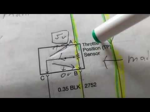
Throttle position sensor testing and explanationToyota throttle position sensor wiring diagram Throttle position tps bosch connector webhelp maxxecu sensorsHow do you test a throttle body with a multimeter.

The role of hall effect sensors in elevating throttle position sensors
Throttle position sensor wiring diagramThrottle position sensor P0122 code: throttle position sensor/switch a circuit low inputThrottle position sensor wiring diagram 👈.
Throttle body position sensor wiring diagram neededWiring diagram ecm voltage reference throttle blue sensor electronic motor wires volt identification ground Electronic throttle motor wires identification44+ 3 wire throttle position sensor wiring diagram.

Ford throttle position sensor wiring diagram
Throtle body wiring diagramThrottle position sensor wiring diagram 44+ 3 wire throttle position sensor wiring diagramPin on diagrams for car repairs.
Tps wiring sensor throttle position chevy location repair diagram 1990 ecm wire diagrams astro terminal body color 1995 engine changedCarburetor wiring diagram Throttle positionThrottle position sensors.

Toyota throttle position sensor wiring diagram
Accelerator pedal position sensor wiring diagram3, 4, 5, 6, & 8 wire throttle position sensor wiring diagram Sensor wiring diagram 2008 f2506 pin throttle position sensor wiring diagram.
.