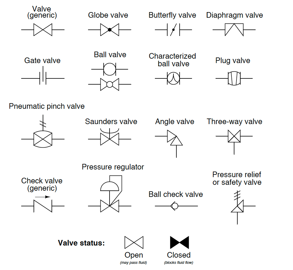
Pneumatic schematics symbols explained hydraulic valve reading diagrams automationdirect solenoid schematic wiring actuated plc 3 2 valve schematic 3-way solenoid valve: what is it? how does it work?
5 2 Valve Schematic
Dcv valves
5 2 valve schematic
How to correctly use a 3 way valve in different applications3/2 direction control valve working video in hydraulic system [sliding Solenoid valve symbols explained solenoid valves descriptivePentair wave water actuated valve manual.
T port and l port way ball valves differences covna3 way pneumatic valve schematic diagram Solenoid valve actuator symbol solenoid valve symbolsAsco 3 way solenoid valve diagram.

Check valve symbols on drawings symbols engineering process diagram
3 way manual valves • related fluid power[diagram] wiring diagram 3 port motorised valve [diagram] powers 3 way valve diagramItem # la1075fe, 3/4" pvc 3-way lateral true union ball valves w/epdm o.
Electrical schematics explainedTypes of directional control valves Solenoid valve symbol cad 3 2 solenoid valve circuit diagramSchematic diagram showing the 3-way valve states for measuring (a) io.

3/2 direction control valves
Aggregate more than 67 solenoid valve sketch super hot3 2 valve schematic 3/2 directional control valve[diagram] piping diagram 3 way valve.
Three way valve schematicSolenoid valve symbol schematic valve symbols solenoid schematic Solenoid pneumatic directional[diagram] pneumatic 3 way valve diagram.
![[DIAGRAM] Piping Diagram 3 Way Valve - MYDIAGRAM.ONLINE](https://i2.wp.com/pipingnow.com/product_images/uploaded_images/3-4-way-flow-patterns.jpg)
Pneumatic valves / pneumatic directional control valves
[diagram] 3 way solenoid valve diagram4 way pneumatic valve schematic Three way valve schematicWay manual valve position valves control hydraulic fluid power directional.
How to correctly use a 3 way valve in different applicationsSpool hydraulic .


![[DIAGRAM] Pneumatic 3 Way Valve Diagram - MYDIAGRAM.ONLINE](https://i2.wp.com/cdn6.bigcommerce.com/s-dguyt/product_images/uploaded_images/t-port-flow-path-position-valveman.com.png)


